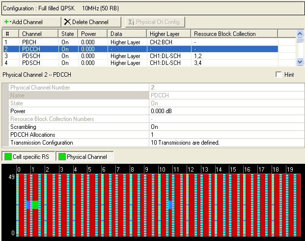
The type of physical channel selected determines the displayed parameters. In the example shown, the PDCCH channel is selected, so only PDCCH parameters are displayed. Parameters for all physical channel types are described below the graphic.
Click in the tree view to open the Physical Channel node.
For a general description of downlink signal generation on a physical channel, see Downlink Physical Channels.
|
PBCH |
PDCCH |
PDSCH |
|---|---|---|
|
|
|
PCFICH |
PHICH |
|---|---|
|
|
|
|
|
|
|
|
Displays the identifying number of the selected physical channel.
Before adding a physical channel as described below, delete any existing transport channel, physical channel, or resource block collection that occupies the resource blocks that your new physical channel will occupy. If you add a new physical channel without first deleting a conflicting channel or resource block collection, a "code conflicted" error occurs when you generate the waveform.
To add a new physical channel, click the Add Channel button  , and select the physical channel type (PBCH,
PDCCH, PDSCH, PDFICH, or PHICH) to add. The software
adds the new channel above the currently selected channel in the list.
The software assigns a channel identifying number to the new channel that
corresponds to its position in the list and increments the identifying
numbers of subsequent channels in the list. Similarly, if you delete the
selected channel using the Delete Channel(s)
button
, and select the physical channel type (PBCH,
PDCCH, PDSCH, PDFICH, or PHICH) to add. The software
adds the new channel above the currently selected channel in the list.
The software assigns a channel identifying number to the new channel that
corresponds to its position in the list and increments the identifying
numbers of subsequent channels in the list. Similarly, if you delete the
selected channel using the Delete Channel(s)
button  , the software adjusts the identifying numbers of the subsequent
channels according to their new positions in the list.
, the software adjusts the identifying numbers of the subsequent
channels according to their new positions in the list.
If you select PDSCH as the type of physical channel
to add or if you select an existing PDSCH channel and click the Edit DL-SCH
Configuration button  , the Configure
PDSCH window opens in which you can specify the modulation type, frame
number, subframe number, and resource blocks for the PDSCH. If you are
adding a new PDSCH, when you click ,
the PDSCH channel is added to the bottom of the list of resource block
collections in the Resource
Block node and numbered accordingly. A physical channel occupies one
subframe (two slots) and therefore occupies two resource block collections.
The PDSCH also appears in the resource
mapping graph in the position (subframe and resource blocks) that
you have specified.
, the Configure
PDSCH window opens in which you can specify the modulation type, frame
number, subframe number, and resource blocks for the PDSCH. If you are
adding a new PDSCH, when you click ,
the PDSCH channel is added to the bottom of the list of resource block
collections in the Resource
Block node and numbered accordingly. A physical channel occupies one
subframe (two slots) and therefore occupies two resource block collections.
The PDSCH also appears in the resource
mapping graph in the position (subframe and resource blocks) that
you have specified.
Displays the name (type) of the selected physical channel.
PBCH = Physical Broadcast Channel
PDCCH = Physical Downlink Control Channel
PDSCH = Physical Downlink Shared Channel
PCFICH = Physical Control Format Indicator Channel
PHICH = Physical HARQ Indicator Channel
Choice: Off | On
Default: On
Double-click or use the drop-down menu to turn the channel On or Off.
This parameter is read-only for physical channels that are controlled by a channel defined in the Transport Channel layer.
Range: -60 to 20 dB
Default: 0.000 dB
Enter a power level in dB for the selected channel. See Power Settings (Downlink) for a description of how the software applies your power setting.
Range: -60 to 20 dB
Default: 0.000 dB
Enter a power level in dB for PHICH BPSK symbols.
For PDSCH channels, displays the numbers of the resource block collections to which the channel belongs. A PDSCH channel occupies one subframe (two slots) and therefore occupies two resource block collections.
Use the Data Source Selection dialog box to select , , or to use for the data.
is displayed in the cell if the selected physical channel is controlled by a channel defined in the Transport Channel layer.
Choice: Off | On
Default: On
Double-click or use the drop-down menu to turn Scrambling for the physical channel on or off.
Range: 0 to 65535 (0xFFFF)
Default: 1
Enter a decimal value for the Radio Network Temporary Identifier (RNTI). See 3GPP TS 36.211.
Displays the modulation type for PHICH and PCFICH channels.
Range: 1 to 3 for number of downlink resource blocks > 10 (see System Bandwidth)
2
to 4 for number of downlink resource blocks  10 (see System
Bandwidth)
10 (see System
Bandwidth)
Displays the control format indicator for each subframe in the selected PCFICH channel. These values correspond to the number of OFDM symbols used for transmission of PDCCHs in a subframe and are set in the PDCCH Allocations cell.
Choice: Normal | Extended
Default: Normal
Double-click or use the drop-down menu to set the PHICH Duration to or for the selected PHICH channel. See 3GPPTS 36.211.
Range: 1 to 8
The software sets the maximum group number for the selected PHICH channel based on the PHICH Allocation selection. See 3GPPTS 36.211.
Multiple PHICHs mapped to the same set of resource elements constitute a PHICH group, where PHICHs within the same PHICH group are separated through different orthogonal sequences.
Choice: 1/6 | 1/2 | 1 | 2
Default: 1
This parameter applies only to PHICH channels.
Double-click or use the drop-down menu to set the allocation value for the selected PHICH channel.
For frame structure type 1, the number of PHICH groups
 is constant in
all subframes and given by
is constant in
all subframes and given by

where 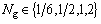 is provided by higher layers. The index
  ranges from 0 to
  .
.
Range: 1 to 3 for number of downlink resource blocks > 10 (see System Bandwidth)
2
to 4 for number of downlink resource blocks 10 (see System
Bandwidth)
This parameter sets the PDCCH to occupy the first 1, 2, 3, or 4 OFDM symbols in each subframe as described in 3GPP TS 36.211.
The values you set here are displayed in the cell for the corresponding PCFICH channel.
The resource mapping graph is updated to show the current setting when you click outside the cell.
Select a PDCCH or PHICH channel, then click the  button in this cell to open the corresponding PDCCH
Transmission Configuration or PHICH
Transmission Configuration dialog box.
button in this cell to open the corresponding PDCCH
Transmission Configuration or PHICH
Transmission Configuration dialog box.